
i've decided to make DSP 01 an open source project.
you can find all the files here.
this is not one of those open source projects where i misdirect you to an indecipherable Github folder. i've organized my files in a clear way. i want you to be able to see exactly what i did, how i did it, and how to do it yourself.
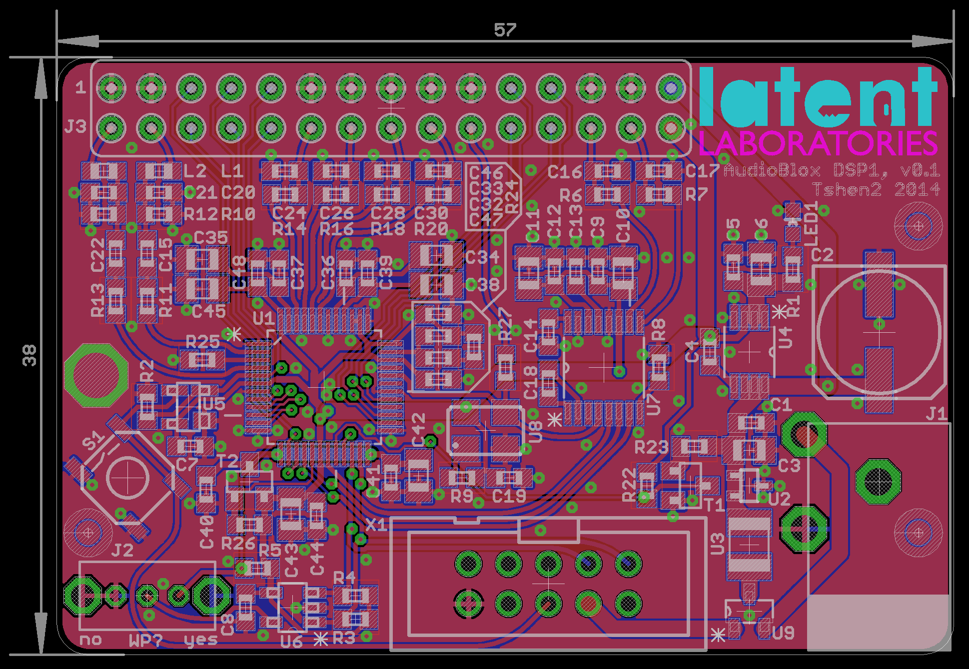
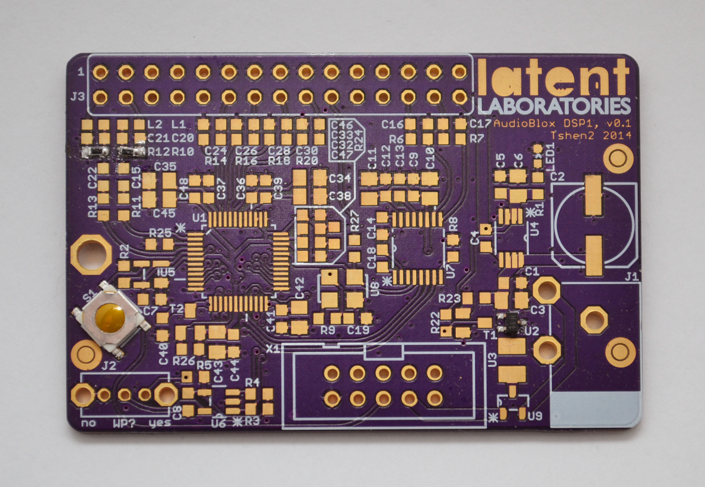
i've put all my design files on an open source page where you will find everything you need to build yourself a DSP just like this one. you are welcome to.
the faster i give away these projects, the less reason i have to stand still. it's not like i will sell it anyways - i already have a (massive) day job, and much bigger ideas to chase. so this one is for you - build it, learn from it, use it everyday.
there are no strings attached. this is a gift.
Tshen2 2014