

DSP architecture, version 1.
here are the goals i set for the DSP:
- stereo inputs with clip-detect lights. DSPs are notorious for gain staging problems, so i wanted the user to give it the largest possible signal without clipping the inputs.
- six outputs to support stereo triamplified speakers or stereo biamplified speakers + subwoofer.
- modular user interface for an arbitrary configuration of switches or dials.
- easy to integrate with off-the-shelf amplifier boards, into a single chassis.
- can be powered by a single-cell Li-ion battery for portable use.
the heart of my DSP is Analog Device's ADAU1701. it is an amazing piece of work. two 24-bit ADCs and four 24-bit DACs. integrated 50MHz DSP core. self-boot capability. auxiliary 8-bit ADC to read potentiometers.
coming from a place of analog skepticism, i expected it to sound awful. i planned to use digipots on the outputs to do volume control in analog, and avoid digital attenuation. i threw in a microcontroller (ATtiny) for clip-detect and to adjust the digipots. i added output amplifiers.
then i actually listened to the evaluation board and it sounded fine. the digipots and output amplifiers were completely extraneous. clip-detect could be built into the DSP itself - i could leave out the microcontroller too. this led to a much simplified version 2:

DSP architecture, version 2
this includes:
- ADAU1701: the DSP core, including 2 inputs and 4 outputs.
- AK4430: additional 2 outputs, for 6 outputs total.
- DIR9001: SPDIF receiver to receive digital audio.
- USBi: Analog Device's SigmaDSP programmer.
after more listening, i decided the SPDIF input was also extraneous. i would include the hooks to add it later. it could live on the modular user interface, and connect through a header.
these changes led to version 3:

DSP architecture, version 3
why a 24.576MHz clock? the AK4430 delivers maximum THD+N if your master clock is at least 512*(sample rate). at a 48kHz sample rate, that's a minimum clock of 24.576MHz. this relationship exists because the AK4430 uses a switch-cap output filter. like all switch-cap filters, its corner frequency is affected by the clock frequency.
why the AK4430 at all? it's good enough, and quite cheap, and runs at 3.3V.
now let's calculate our power requirements:

looks like our worst-case current draw is about 200mA. what about power supply noise?
ADAU1701 power supply noise requirements:
- PSRR is 50dB at 1kHz, with 200mV signal on AVDD
- FS (full scale voltage) is 2.5 Vpp
- SNR is 104dB
- PSRR noise is PSN (power supply noise) - 50dB
- PSN - 50dB << FS - SNR
- PSN << FS - 54dB
- PSN << 5 mVpp
AK4430 power supply noise requirements:
- PSRR is 62dB at 1kHz, 50mVpp signal on VDD and CVDD
- FS is 5.66 Vpp
- SNR is 104dB
- PSN - 62dB << FS - SNR
- PSN << FS - 42dB
- PSN << 40 mVpp
the ADP3335 LDO has excellent load regulation, 500mA maximum output current and a peak voltage noise of under 0.3 mVpp. it will do fine.
i'll also throw on a 30-pin header to connect the Main Board and the UI Board.
time to bang it out!

a picture is worth a hundred hours.
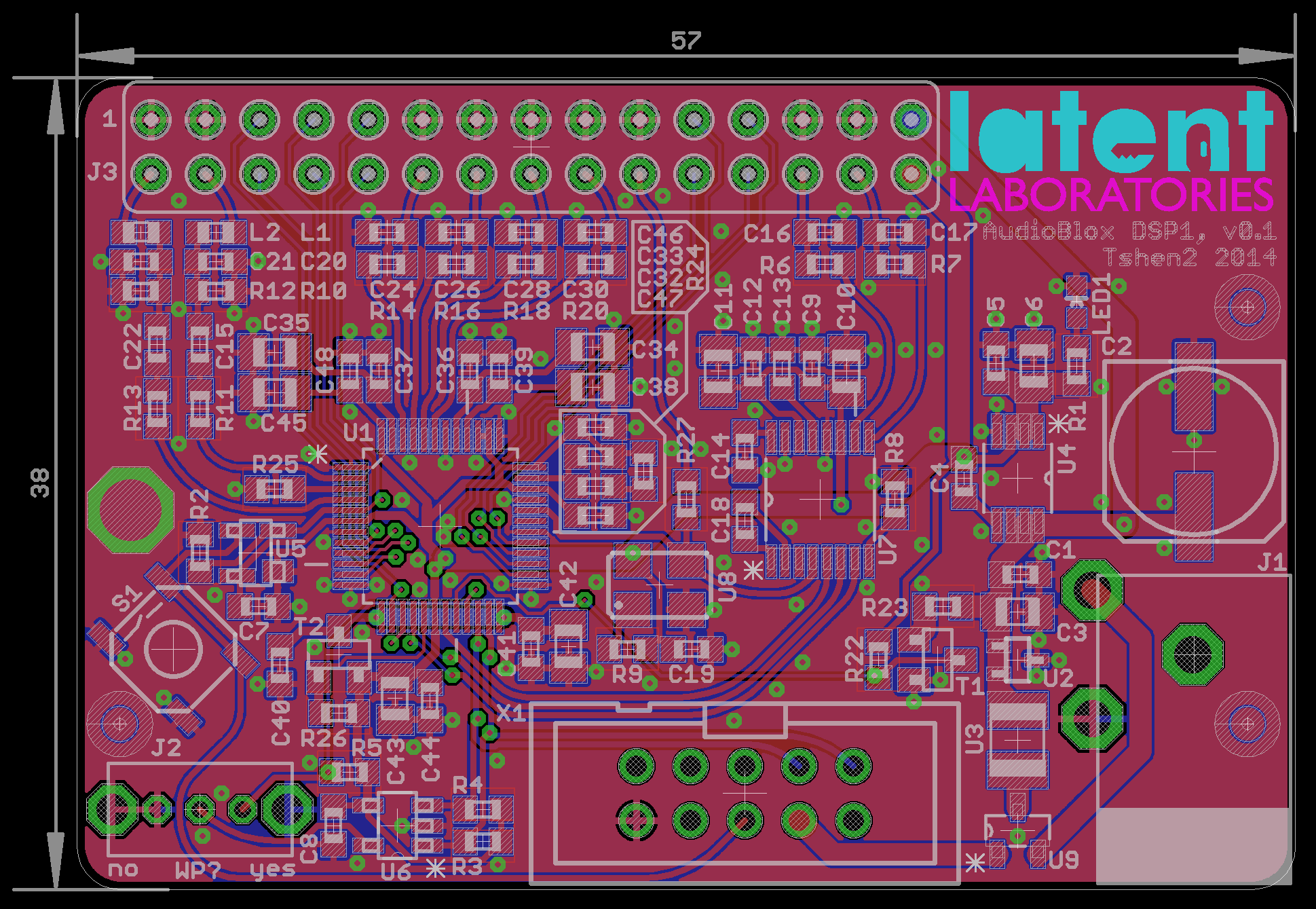
two pictures is worth 200 hours.
OSHpark time!
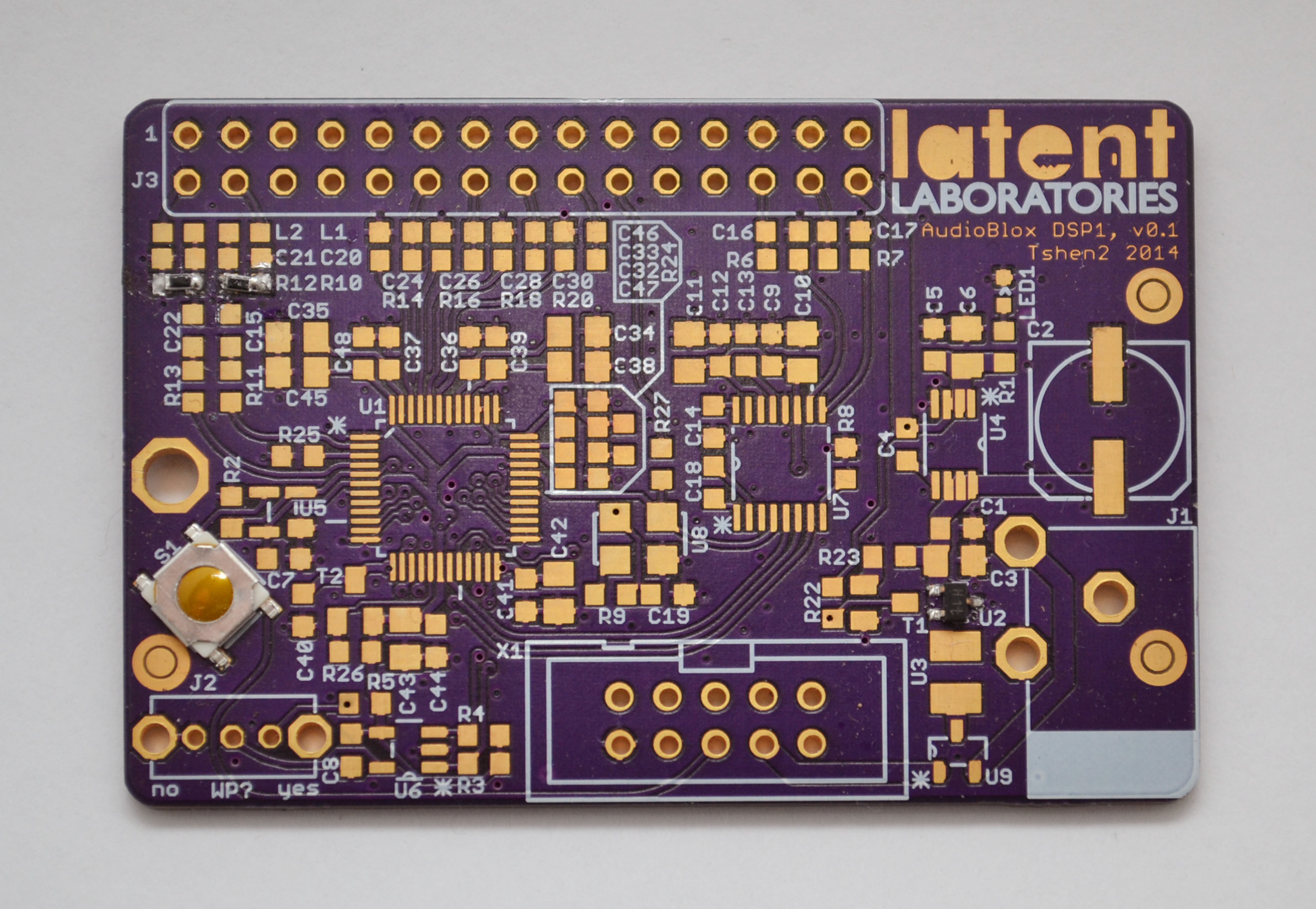
did it work? (yes)
next update, i will describe the user interface and lasercut chassis.
Tshen2 2014


