the chassis which holds the DSP must do these obvious, practical things:
- it must be dead silent.
- it must keep itself cool.
- it must accept 24V DC power.
- it must have six amplifier outputs.
- it must accept digital & analog audio inputs.
- it must have controls for volume, input mixing and other programmable features.
it must also do these less-obvious practical things:
- it must not waste.
- it must explain itself.
- it must want to be used.
so let's analyze these needs in that order.
it must be dead silent.
it must keep itself cool.
silent things don't use cooling fans. but amplifiers without cooling fans tend to heat up. we are using Class-D amplifiers of course, but the risk is still real.
the amplifier board i have picked was built to use a fan, but i am not pushing it anywhere near its rated limits. if i remove the fan, i will be relying on convection to cool the amplifier. the chassis must hold the amplifier upright to maximize convective air flow.
it must accept 24V DC power.
it must have six amplifier outputs.
it must have accept digital & analog audio inputs.
it must have controls for volume, input mixing and other programmable features.
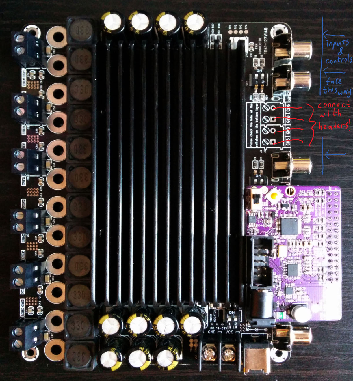
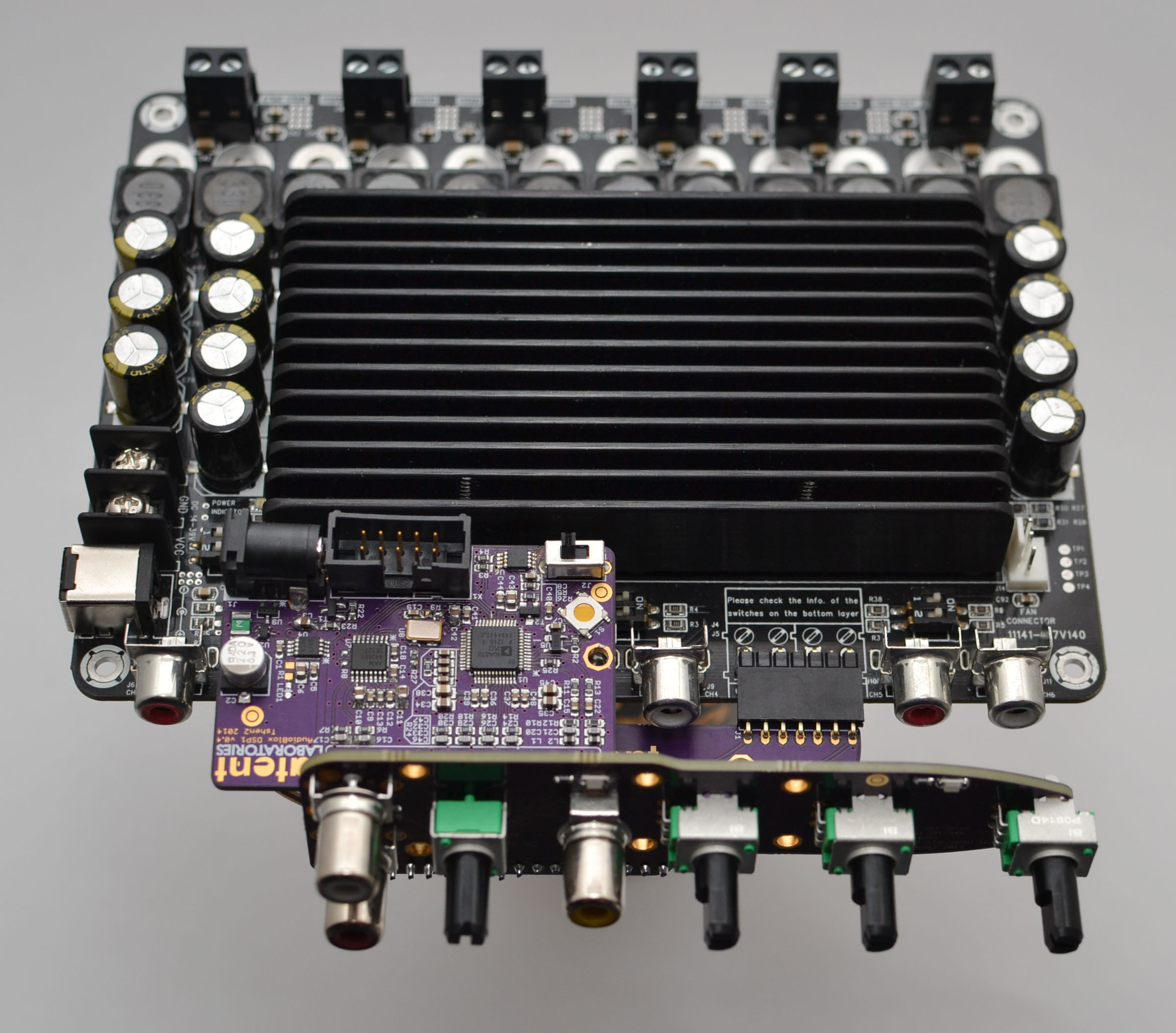
consider the layout of the amplifier & DSP.

inputs & controls are below and outputs are above. the DC power jack is to the left.
the amplifier's heat sink must be upright for good cooling, with extensive venting for airflow. hence the DC power jack will be either above or below the chassis. it should clearly be below, or we'd have a power jack sticking out the top of the chassis. the horror!
so here we are:

it must not waste.
it has no more internal volume than it needs. that means less surface area, which means less plastic.
acrylic and brass are already beautiful. we will not use glue or paint.
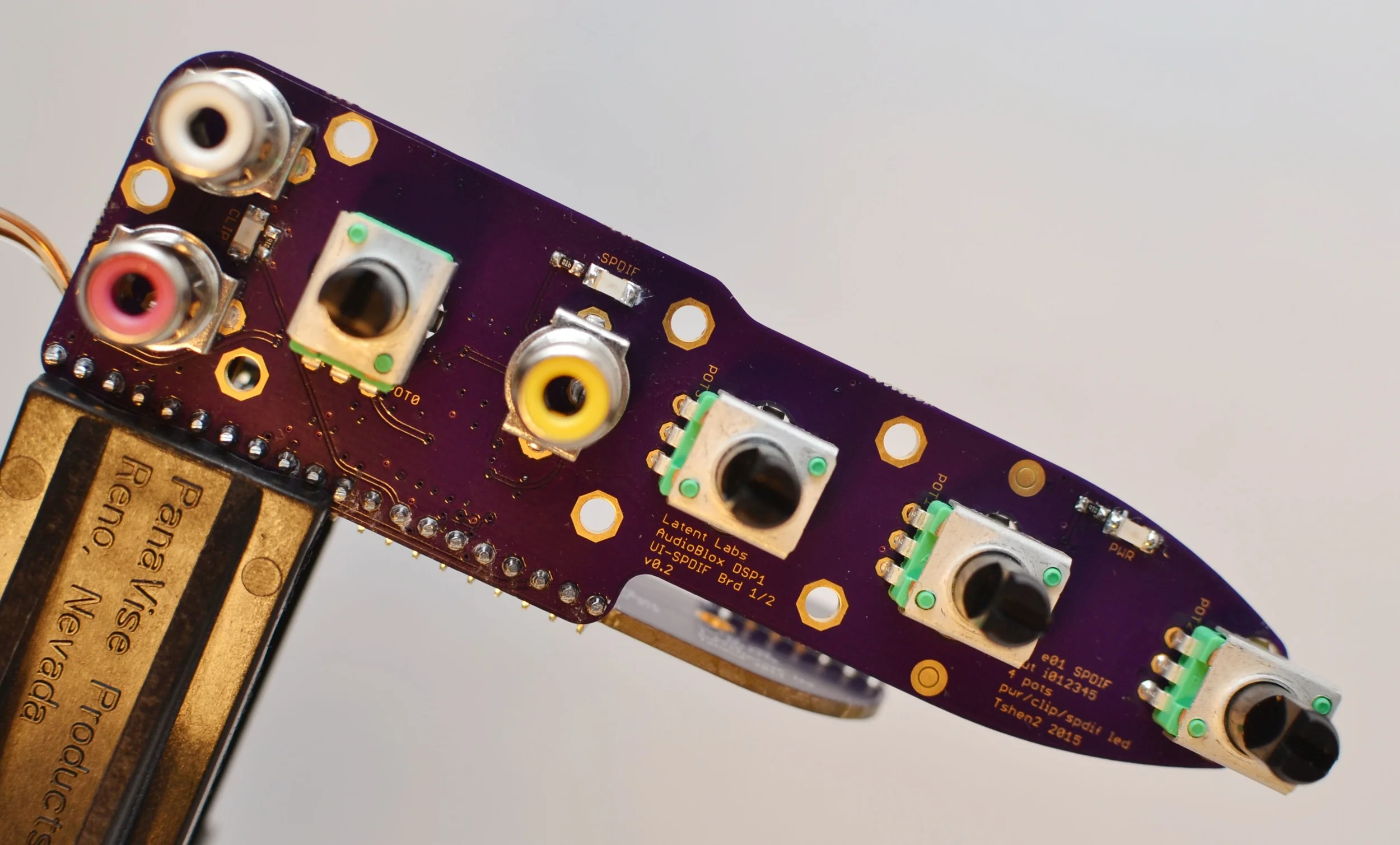
it must explain itself.
the volume control and mix control knobs both control loudness - they can be the same color.
the multipurpose adjust 1 and adjust 2 knobs will be a different color.
the mix control knob is between the digital & analog inputs. turning it up (towards the digital input) or down (towards the analog input) has the expected effect.
the front panel contains LEDs which indicate power, SPDIF status and analog signal clipping.

it must want to be used.
the chassis is quite small. it will probably sit on a low table or the floor, between two speakers. it will probably be below the user.
to use the inputs & controls, the user will have to look down at it. it is only polite that it look back up.
the chassis is built as a box with angled feet, so that it looks up by 10 degrees.
various lines on the front-plate are positioned to harmonize and emphasize this angle.

this is how i see it.
Conclusion
after all that, what do i end up with? this:
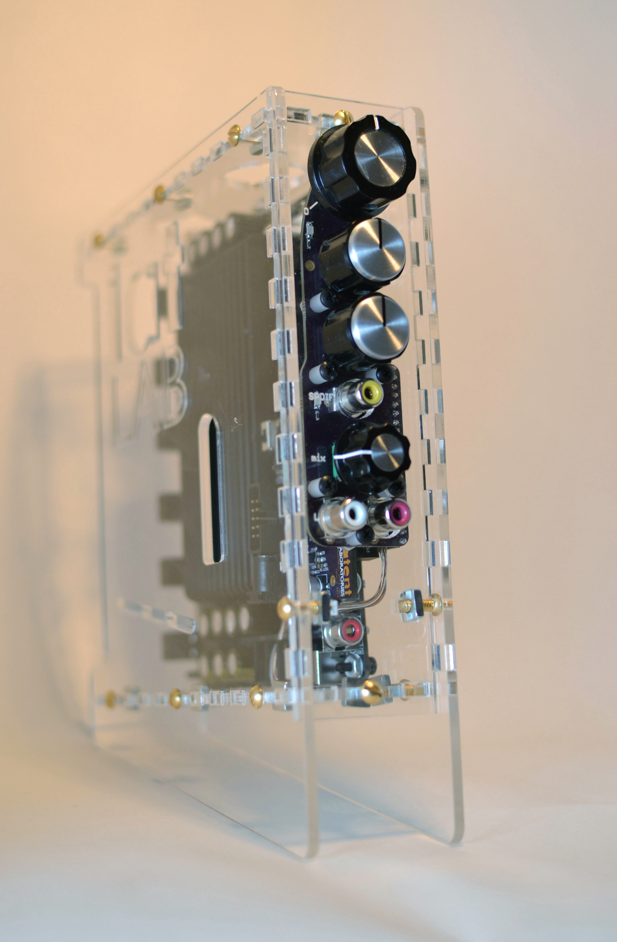


you can see the venting holes above and below - the lat LAB logo is also a vent.
so let's install it!

DSP 01 in new chassis, with rainbow programming cable
next update: i actually do something with it.
Tshen2 2015